Stabilizers
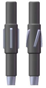
WELDED BLADE CONSTRUCTION – STRAIGHT / SPIRAL RIB
| Hole Size Inches | Shoulder to Shoulder Length Inches |
Body Diameter Inches | Part Number Straight Rib Construction |
Part Number Spiral Rib Construction |
| 6 1/4 | 42” | 5 | 35340 | 35440 |
| 6 3/4 | 42 | 5 ½ | 35341 | 35441 |
| 7 7/8 | 32” | 6 1/4 | 35342 | 35442 |
| 7 7/8 | 42 | 6 1/4 | 35243 | 35443 |
| 9 | 32” | 7” | 35300 | 35400 |
| 9 | 42” | 7” | 35301 | 35401 |
| 9 | 32 | 7 5/8 | 35302 | 35402 |
| 9 | 42 | 7 5/8 | 35303 | 35403 |
| 7 7/8 | 32” | 7 5/8 | 35304 | 35404 |
| 7 7/8 | 42 | 7 5/8 | 35305 | 35405 |
| 7 7/8 | 50 | 7 5/8 | 35306 | 35406 |
| 9 7/8 | 42 | 8 5/8 | 35307 | 35407 |
| 9 7/8 | 50 | 8 5/8 | 35308 | 35408 |
| 10 5/8 | 32” | 8 5/8 | 35309 | 35409 |
| 10 5/8 | 42 | 8 5/8 | 35310 | 35410 |
| 10 5/8 | 50 | 8 5/8 | 35311 | 35411 |
| 11 | 32” | 9 1/4 | 35312 | 35412 |
| 11 | 42 | 9 1/4 | 35313 | 35413 |
| 11 | 50 | 9 1/4 | 35314 | 35414 |
| 12 1/4 | 32 | 8 5/8 | 35315 | 35415 |
| 12 1/4 | 42 | 8 5/8 | 35316 | 35416 |
| 12 1/4 | 50 | 8 5/8 | 35317 | 35417 |
| 12 1/4 | 32” | 9 1/4 | 35318 | 35418 |
| 12 1/4 | 42 | 9 1/4 | 35319 | 35419 |
| 12 1/4 | 50 | 9 1/4 | 35320 | 35420 |
| 12 1/4 | 32” | 9 5/8 | 35321 | 35421 |
| 12 1/4 | 42 | 9 5/8 | 35322 | 35422 |
| 12 1/4 | 50 | 9 5/8 | 35323 | 35423 |
| 12 1/4 | 32 | 10 3/4 | 35324 | 35424 |
| 12 1/4 | 42 | 10 3/4 | 35325 | 35425 |
| 12 1/4 | 50 | 10 3/4 | 35326 | 35426 |
| 13 3/4 | 32 | 10 3/4 | 35327 | 35427 |
| 13 3/4 | 42 | 10 3/4 | 35328 | 35428 |
| 13 3/4 | 50 | 10 3/4 | 35329 | 35429 |
| 13 3/4 | 32 | 11 3/4 | 35330 | 35430 |
| 13 3/4 | 42 | 11 3/4 | 35331 | 35431 |
| 13 3/4 | 50 | 11 3/4 | 35332 | 35432 |
| 15 | 32” | 13 3/8 | 35333 | 35433 |
| 15 | 42 | 13 3/8 | 35334 | 35434 |
| 15 | 50 | 13 3/8 | 35335 | 35435 |
| 16 | 32” | 13 3/8 | 35336 | 35436 |
| 16 | 42 | 13 3/8 | 35337 | 35437 |
| 16 | 50 | 13 3/8 | 35338 | 35438 |
Ordering instructions: –
1. Hole Size
2. Drill make and model
3. Drill Pipe OD
4. Connections Required –
5. Any special length requirements and wrenching configurations.
The welded blade stabilizer is manufactured with a body of alloy steel with steel wear bars welded to the body and covered with hard metal or tungsten carbide inserts. This stabilizer can have straight or spiral ribs and is effective in soft to medium formations. Thread connection and length alternatives are available on request.